

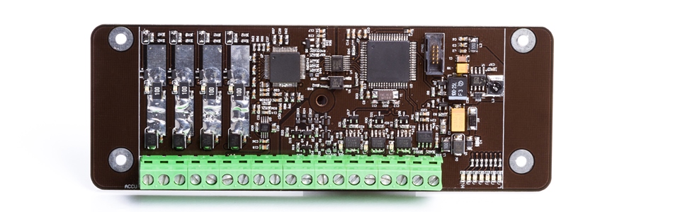


X_BMS_18S
Battery Management System (BMS) upto 18 cells per unit
| Picture |
 |
| Typical Applications |
|
| Processor |
|
| Power Supply |
|
| I/O |
|
| Communication |
|
| Other |
|
Short Description
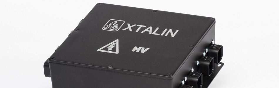
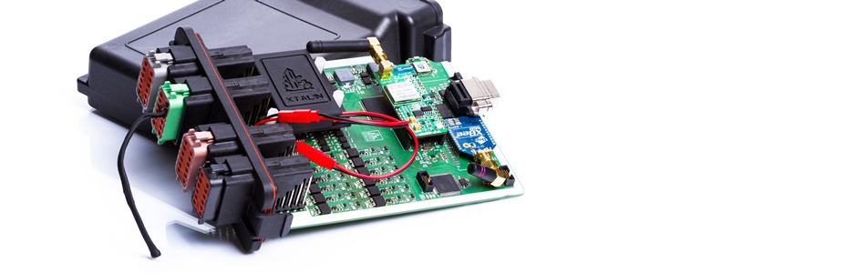
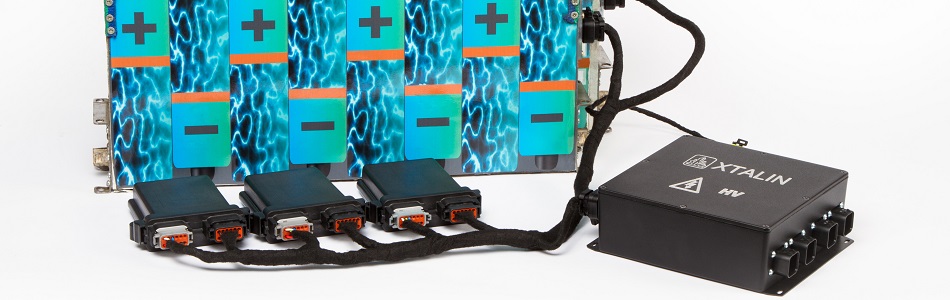
The X_BMS_18S is a lithium battery management system (BMS). A single unit can measure the voltage of up to 18 battery cells is series and the battery temperature at up to 6 points, in addition, multiple X_BMS_18S can be used in a system upto 600VDC. The device works the best with 12 or 18 cells, but is capable of measuring any number of cell voltages between 6 and 18, measuring 4 thermometer sensor signals for 6-12 cells, and 6 thermometer sensor signals for 9-18 cells, depending on the actual wiring.
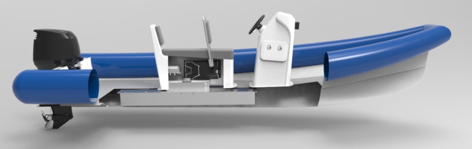
We have successfully applied our BMS in a variety of prototype systems. If necessary, we made hardware and/or software changes to meet the needs of the specific system. This way the X_BMS_18S evolved to its current version. Recommended for systems where space and robustness are the primary consideration.
The X_BMS_18S has 3 separately supplied high-current switchable outputs that control the isolation contactors required for the battery. These outputs are software configurable, by default switching on the first discharge enable contactor, then after pre-charging enabling the second discharge contactor (Drive Relay) and the charge enable contactor (Charge Relay). These outputs can be cascaded with multiple X_BMS_18Ses when used with a larger battery system, so any failure can interrupt the charging or discharging process.
Since >60VDC is already referred to as high voltage for electric vehicles and other battery storage systems, galvanic isolation between the battery and the onboard 12V system is necessary. The X_BMS_18S provides isolation upto 600V, so you can build a 600V system using 8 devices.
The device uses CAN bus communication protocol, which is common in the automotive industry and in control systems. Cell voltages are reported with 10mV and temperature values at 1°C resolution. Actual measurement accuracy is <2mV and <0.5 ° C, but such resolution is not required in most applications, only for BMS own internal calculations, such as passive balancing.
We developed a CAN-Bootloader for our devices which makes it possible to reprogram the devices via the system communication bus without disassembling any part of the system. That greatly accelerates the development of prototypes and the possible subsequent software updates of the finished systems.
Depending on the system, the charge process may be controlled by the X_BMS_18S or the X_VCU. The charge equalization (balancing) between the cell voltage levels is always performed by the X_BMS_18S with a (configurable) current.
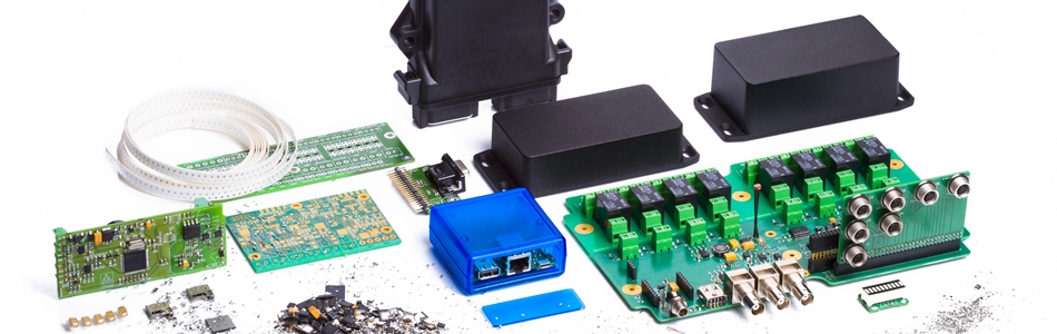
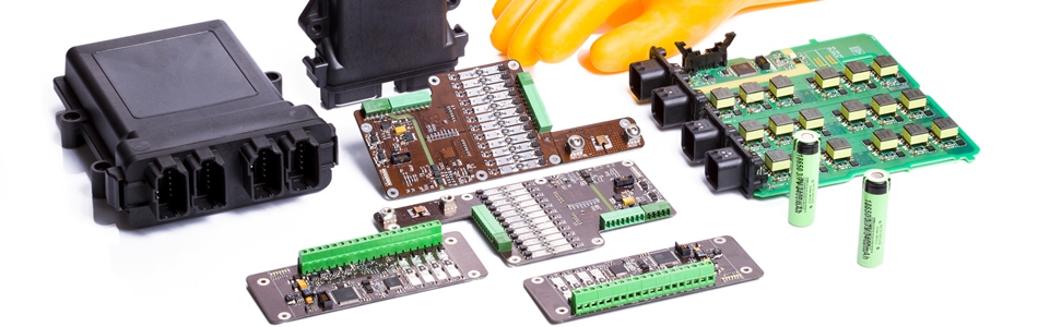
Other advanced electronics are required for safe, reliable, user-friendly operation of battery systems, such as:
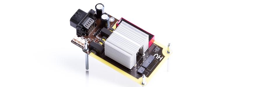
- DC-rail Pre-charge Circuit (X_Precharge)
- DC-rail Discharge Circuit (X_Discharge)
- SoC Estimator / Energy Meter Electronics & Sensor (X_EM)
- 12V Battery Monitoring and Power Distribution Module (X_PDM)
- Many more (isolation test, collision detection,…)
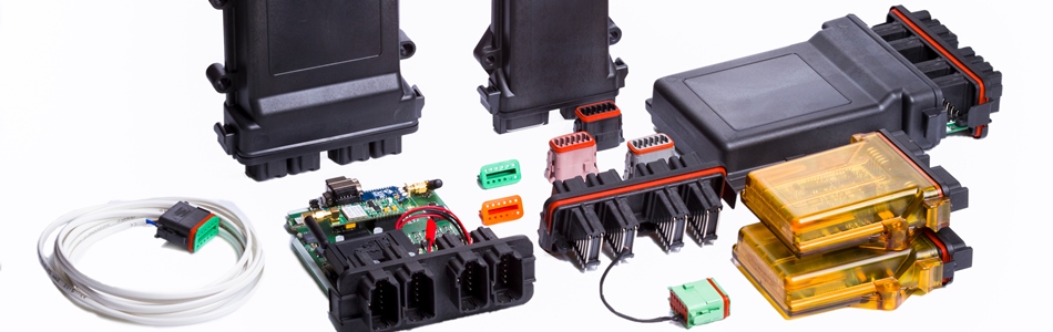
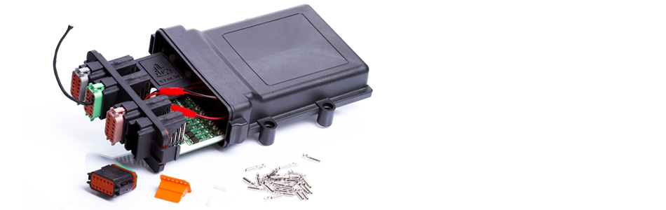
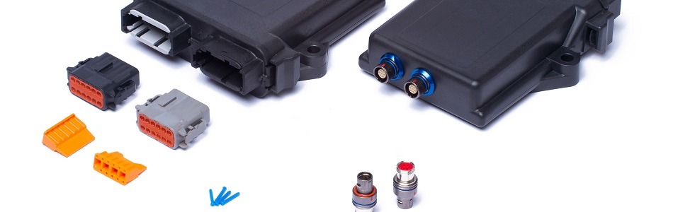
The X_BMS_18S package includes:
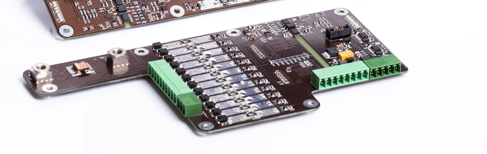
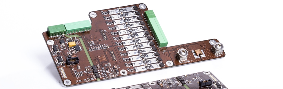
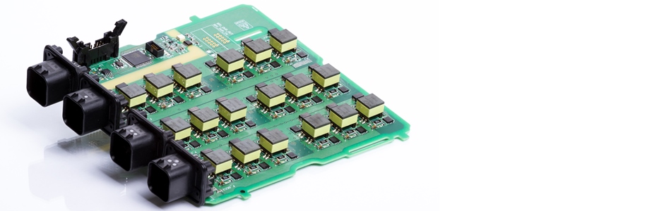
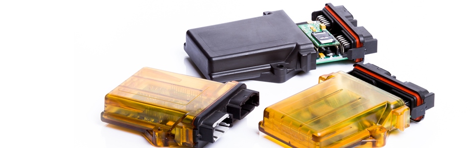
- Printed circuit board with IP67 enclosure
- Mating connectors (IP67), 4 pieces, with contacts
- Pre-programmed BMS software, in which the following parameters can be customized
- Minimum and maximum cell voltages
- Minimum and maximum discharge temperatures
- Minimum and maximum charge temperatures
- CAN bus speed and ID
- CAN-Bootloader software module for convenient software update
We can customize the software (and the hardware) for any specific application. Request a unique quote at This email address is being protected from spambots. You need JavaScript enabled to view it..